Sunday 30 November 2014

Open day at Marple Locks

The Canal and River Trust today held an open day at Marple, showcasing work they are carrying out on one of the locks in the Marple flight on the Peak Forest Canal, and also work on Marple Aqueduct. I heard about this through an interesting talk last Thursday evening, given to our Local History Group (at Wilmslow Guild) on Mellor Mill and Samuel Oldknow, by Bob Humphrey-Taylor. Bob even came dressed as entrepreneurial mill owner Sam Oldknow and the first part of his talk was about 'his' life (Samuel Oldknow's), the second part being about the project he (Bob Humphrey-Taylor) is involved in with the Mellor Archaeological Trust to restore the site of Oldknow's Mellor Mill which burned out in 1892. For more information on Mellor Mill, click on this link.

Samuel Oldknow's Mellor Mill, burned out in 1892

Bob told us of the Mellor Archaeological Trust's efforts to gain a Heritage Lottery Fund (HLF) Grant. Their first application was not successful so they tried again. Their second application also failed, but only because the Canal & River Trust had also put in a bid for HLF funding for the restoration of Marple Aqueduct. The HLF advised the Archaeological Trust and the Canal & River Trust that as both projects were in the same locality, and both concerned Samuel Oldknow (who had been active in promoting the Peak Forest Canal both for his mill and for his lime industry at Marple), they should submit a joint £2.3 million bid entitled Revealing Oldknow’s Legacy'. This they did, and were successful. Early next year our Local History Group will visit the site of Mellor Mill so Bob can show us around. In the meantime, he told us of today's event which is concerned with the Canal & River Trust's part of the joint project, so I went along to have a look.

The works at Marple Aqueduct are supported by a £1.5 million share of the HLF 'Oldknow' funding, together with public donations. Revealing Oldknow’s Legacy' aims to revive the legacy of one of the leading industrialists of the early cotton industry, by protecting and opening up three important historic sites he was closely associated with; Marple Aqueduct, Mellor Mill and Marple Lime Kilns.


While the Canal & River Trust is repairing Marple Aqueduct, they are also doing maintenance work on the number two lock in the Marple flight, as this has been leaking water. Today's open day concerned both work on the lock, and on the aqueduct.

As usual, please click on any picture for a larger image.


 It's about a mile walk from the road by lock 9 at Marple down the flight to lock 2 where the work was taking place, but it was bright and dry today, pretty good for the last day of November, so the walk was enjoyable

Not only was the lock and pound below it drained, but the Canal & River Trust had cleared the debris out of it and set up a stairway so visitors could easily gain access  

The floor and lower sides of the lock are brick, the remainder built in stone 

The lock gates are about 15 years old and have another 10 years or so of life left in them. They are made of oak, but had started to leak badly hence the new timber put in (where the red colouring is) to seal the closed gate to the lock wall. 

One of the side ducts for emptying or filling the lock, controlled by opening and closing of paddles 

The lock looks pretty deep when empty! Several Canal & River Trust employees were on hand to explain things to visitors. The access stairs can be seen in the background. Strange to think I've navigated a narrow boat through here more than once, suspended several feet above that chap's white helmet!

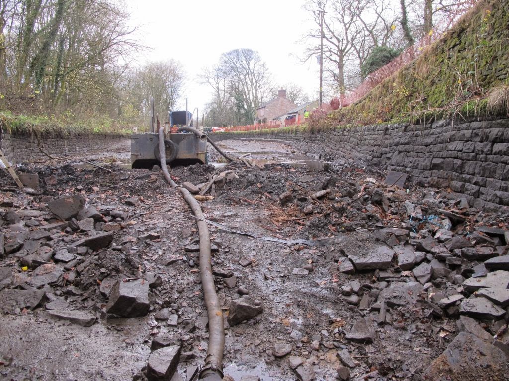
The drained pound below the lock, and some of the debris removed from the lock floor 

Damaged stonework in the side of the pound. This will be repaired while the pound is empty.  

Each oak lock gate, without balance beams, weighs about 1.8 tons 

This timber in the end of the lock floor, where the gates close, is as old as the canal itself, and is softwood; pine in fact! 

The two types of bearing a lock gate sits on; some canals use the one on the left which is let into the lock floor, a corresponding hole being bored in the base of the gate. This canal uses the more common type on the right as a base bearing for the gates. The gates have a short steel spindle let into them which sits in the slightly oval cup, which is attached to the floor of the lock. The ovality allows the gates to move slightly under the pressure of water in the lock as it fills, for a good seal against the stonework.

This is an overflow which prevents the water level in the pound above the lock getting too high and flowing over the top of the lock gates. Interestingly, Marple locks have weirs adjacent to each lock to allow excess water to bypass the lock, so one can only presume that the weirs were added when these overflows proved inadequate for the task.

A side paddle for filling the lock. These are made of elm, and this one has just been renewed. I was told that the lifting mechanism might fail as frequently as more than once a year; not a major problem as long as the paddle falls to the 'closed' position and does not jam open, wasting water through the lock.

A similar paddle on a lock gate, except this one is made of plastic. It, too, has just been renewed and its lifting mechanism is yet to be re-connected. This isn't the best of designs, as the two paddles hit each other when the gate is fully open! 

A view of the stairway, complete with 'landings', to allow public access to the lock works 

Looking the other way, upstream towards the full pound above the lock. The water is held back by stop planks slid down grooves in the stonework of the lock wall. When the planks are first inserted the joints between them leak copiously. The best way yet found to seal them is to cut a small nick in one end of the bottom edge of each plank, on the 'upstream' side, then to sprinkle ashes into the water. The ashes get drawn into the nicks and then along the gaps between the planks forming a watertight seal. 
I was told it takes only seconds for the planks to seal, and one can see first the top gap sealing, then the next one down, and so on until all the gaps are sealed. Apparently boiler ash is best for this when they can get it, so I told them that any heritage railway would be delighted if someone rolled up with a big truck and took away their ash pile!  

The drained pound below the lock, looking towards lock no.1 of the flight. Marple aqueduct is beyond that lock.  

Bob Humphrey-Taylor (AKA Samuel Oldknow) and friend. Did they have sunglasses in the 18th century?

The aqueduct information board. Please click on the image to enlarge it to legible size. 

The railway viaduct runs alongside the aqueduct, both over the river Goyt in its deep valley 

This must be a Sunday 'engineering diversion' off the Hope Valley line; an East Midlands Trains class 158 diesel multiple unit on a Norwich to Liverpool service crosses the Goyt viaduct, alongside the tranquil waters of the Peak Forest Canal on its aqueduct

Work to be done on the aqueduct includes re-pointing with lime mortar, and painting the metalwork. It is also intended to cut back the tree growth of recent years to restore the views of this magnificent structure, and to build a viewing platform for that purpose. I wish Network Rail would follow suit and remove the excessive tree growth of recent years alongside our railway lines. It would certainly make the 'leaves on the line' in autumn less of a problem as well as improving the view.  

A last look up the valley of the Goyt through the arches of the railway viaduct, seen from the canal aqueduct.

No doubt if Samuel Oldknow had been around at the time the railways were being built, he'd have been promoting those too! As it is, having seen today the lovely Peak Forest Canal he championed, I look forward to our Local History Group's visit to the site of his major achievement - Mellor Mill.


.

Tuesday 25 November 2014

A new blind for The Great Wheel at Quarry Bank Mill

Last week the Norfolk Millwrights were at Nether Alderley Mill, as described in the previous post. This week they are at our parent National Trust property, Quarry Bank Mill in Styal, Cheshire. Quarry Bank is home to The Great Wheel.

The original Great Wheel was designed by Thomas Hewes and installed at Styal in 1818, replacing three earlier wheels. It was over twice the size of its predecessor, developed around 100 hp, and powered Quarry Bank Mill until 1904 when it was replaced by a water turbine which worked until the mill closed in1959.

In 1980 the Quarry Bank Mill Trust restored the mill, and replaced the turbine with a new Great Wheel. This came from Glasshouses Mill in Pateley Bridge Yorkshire and was almost identical to Styal's original Great Wheel. It required a great deal of restoration including casting of a new main shaft. The new wheel had been designed by William Fairbairn, Hewe's apprentice at the time the original Great Wheel was installed. It has operated at Styal since the early 1980s but recently its blind has developed leaks and needed to be replaced.

The blind is the device which controls the amount of water allowed onto the wheel to fill its buckets. It is rather like a large version of a window blind; attached to a rack mechanism it can be raise or lowered between the pen trough and the wheel (which is of the breast shot type) to vary the water flow into the wheel's buckets. Back when the wheel powered the mill machinery the power required would vary depending on the number and type of machines in use at any time, and the blind, controlled by a governor, enabled it to maintain a constant speed irrespective of  loading. The new Great Wheel no longer powers the mill, and we use the blind simply to turn the water supply to the wheel on or off by raising it to cut off the supply, or lowering it slightly to allow enough water onto the wheel to cause it to rotate.

Recently the wheel has taken to running for short periods even when the blind was up. This is because the blind has started to leak and despite being 'up', sufficient water was getting through to slowly fill the buckets and start the wheel turning. The Norfolk Millwrights were therefore engaged to manufacture and install a new blind. I am a volunteer at Quarry Bank and went along there this morning on my little Honda C90 to see what progress was being made.

As ever, please click on any picture for a larger image.

 The last leaves of late autumn hang over Quarry Bank mill meadow this morning. The weir forms the mill pond behind it to power our Great Wheel, the water reaching the wheel through a series of leats and sluices, to the head race which runs under the mill yard. When the water drops off The Great Wheel, having done its work, into the bottom of the wheel pit, it is considerably below river level. It cannot therefore flow back into the river at that point, but follows a tail race tunnel of about 1/3 mile in length which allows the water to re-enter the river at a lower level, further downstream. 

From November to February the mill is closed to the public on Mondays and Tuesdays, hence the deserted mill yard and closed main reception. The Norfolk Millwright's van and my Honda C90 are the only vehicles in the yard this morning.

 A poster explains to visitors to the mill why the Great Wheel is temporarily out of action (click on the picture to make the text legible)

Inside the wheel chamber the millwrights work in the pen trough, drained of water of course. The blind is in two halves which operate together as one continuous blind, and by this morning the old left hand blind had been removed. The replacement, still rolled up, can be seen above the head of the millwright behind the ladder. 

A millwright positions the rolled-up left hand blind prior to installing it 

Here's a view of the front side of the wheel, which normally rotates left to right in this picture, so the buckets (which fill with water, whose weight turns the wheel) are upside down at the left of the picture and on their sides at the top of the picture. By the time they have rotated to the front of the wheel, they will be right way up to receive water from the pen trough past the blind.   

The inside of The Great Wheel. This picture shows how it's a suspension wheel, just about the peak of water wheel design; they didn't get any better or more efficient than this wheel. 'Suspension' means the wheel and its buckets are suspended from the main shaft by relatively thin spokes, rather like a bicycle wheel. This makes the wheel lighter than a conventional heavy-spoked wheel, and therefore more efficient. The secret of the suspension wheel is to take the power not from the main shaft (which would necessitate strong, heavy spokes to transfer the power from the rim to the shaft) but directly from the rim. The gear wheel which engages with the rim to effect this can be seen on the far side of the wheel.

Another advantage of taking the power at the rim rather than from the main shaft is that the speed of rotation of the drive from the wheel is much higher, much closer to that required to drive the mill machinery; conventional water wheels require more gearing to raise the slow speed of the main shaft to the speed required for machinery operation, and this reduces efficiency.  

The new left hand blind, made of buffalo hide with steel strengthening, is readied for positioning. Temporary straps hold it in a rolled-up state, and when these are removed it will unroll and hang like a curtain, ready to be fixed to the metal frame which will raise and lower it. The shaft above the blind and the toothed metal racks in the centre of the picture are part of the raising and lowering mechanism for the blind. 

Entrance to the side of the wheel chamber, closed to the public for the duration of the work 

A view down into the wheel pit showing the as-yet rolled up blind. The large stone weight in the foreground is used to counter-balance the blind, to minimise the physical effort and strain on the rack and frame mechanism to raise the blind. There is a similar counter-weight for the right hand blind. 

Here the blind has been allowed to unroll, and is ready for fixing to its frame 

Here is the old blind, cut into sections to make it easier to remove 

There was plenty of other activity around the mill this morning, mostly concerned with decorating the premises for Christmas. Here a Christmas tree opposite the head gardener's house is dressed.

Next week is the volunteers' Christmas lunch at Quarry bank. Before tucking into that, I'll nip across to the wheel chamber to see how the millwrights are progressing with replacement of the blind. By then, they might even have finished and gone!


.

Tuesday 18 November 2014

Annual maintenance at Nether Alderley Mill

It's November again and time for the millwrights to visit the National Trust's Nether Alderley Mill, where I am a miller and a guide, for the annual check of the machinery.

Please click on any picture for a larger image.

Norfolk Millwright Alliance van outside the mill this morning

The initial news wasn't good; a large stone supporting the bearing for the main vertical shaft in the mill has tilted slightly, no doubt due to undermining by the running water in the mill basement. Apparently this was a fault known about when the mill was recently restored, and it was put right. But obviously the repair hasn't lasted and the National Trust are to get a structural engineer in to have a look and come up with a better repair scheme.

The pit wheel for the lower water wheel is on the right. It engages with the 'wallower' (the horizontal bevel gear wheel on the vertical shaft), to transfer the water wheel's power via the vertical shaft to the hurst frame (where the power from the upper water wheel and the lower one are combined) and thence to the mill stones. The vertical shaft rests on a bearing, which is located on a supporting stone on the mill basement floor (visible below the wallower in the picture). It is this support stone which has tilted, causing the bearing to wear unevenly and the gears to mesh slightly out of alignment.

The millwrights then designed a repair for a major water leak in the leat (trough) taking water off the upper wheel and feeding it to the lower wheel. After that, it was time to 'split the stones', that is lift the runner mill stone off the bed stone to inspect the milling surfaces.

The first job is to remove the 'furniture' from over the mill stones. The grain hopper has already been removed, and the 'horse' (the frame which supports the hopper) will be next, followed by the 'skirt', the metal shroud around the stones.

Once the skirt is removed, the runner stone is exposed. The 'sweeper' can seen attached to the stone. 

A close up view of the sweeper. As the milled grain (flour) is blown out of the gap between the runner and bed stones (there's quite a strong airflow induced by the stones' rotation blowing from centre to the rim along the wide grooves in the stones, like a centrifugal fan). The flour settles in the gap between the stones and the skirt. The sweeper sweeps it around the stones until it comes to the flour chute, which it drops into.

Note the metal bands around the stone, which holds the individual burr stones together in one homogeneous mill stone. The top band is very deep, and there are two much thinner lower bands. As the stone wears, the lower bands can be removed one at a time to allow the stone to continue to be used. By the time both small bands have been removed and the stone is worn down to the wide band, there is insufficient depth of stone left to continue use (above the burr stones is a deep cap of  plaster of Paris; the burr stone does not extend very far up into the wide metal band). This stone might originally have had three narrow bands, one of which has already been removed. 

When a runner stone is worn too thin to be heavy enough to grind the grain (they weigh about a ton when new) it might be used as a bed stone.

The flour chute. The sweeper sweeps the newly-milled flour round inside the skirt until it comes to this chute, which it falls down to be bagged on the floor below. 

The millwrights feed straps around the runner stone so it can be lifted off the bed stone 

Here is a short video of the runner stone being lifted off the bed stone using block and tackle sets.
Runner stone being lifted off the bed stone

First job, once the stones are separated, is to clean off the flour with brush and vacuum cleaner 

French burr stones like these are made up of sections of stone pieced together, the gaps filled with plaster of Paris. The separate burr stones and 'dressing' of the stones' surfaces can be seen here. The long troughs cut in the stone carry the grain from the centre (the 'eye') towards the edge of the stone aided by the airflow they generate, and do the initial cutting of the grain. They distributes the cut grain over the face of the stones for even milling by the 'stitching' grooves. The metal object above the centre of the bed stone is the 'mace', which supports and drives the runner stone when it is in place above the bed stone. 

These very fine grooves (the stitching) do the fine cutting (milling) of the grain while the wider 'troughs' do the initial cut and distribute it. On our stones some of these stitching areas were polished smooth and the millwrights used an angle grinder with a diamond tipped blade to renew them. Traditionally this job would have been done with a 'mill bill', a sort of wooden adze with a metal cutting tool. That was painfully slow and painful! It induced repetitive strain injuries and bits of stone and metal flying from the tool embedded themselves in the millwrights' arm. The origin of the term 'to show one's mettle' is said to originate from millers wishing to see a mill wright's fore-arm for such evidence of stone dressing experience. 


A Millbill


For an explanation of dressing mill stones, see How to dress mill stones

The steps up to the grain loft are worn by centuries of millers' shoes. One can see which foot they put on each step by the wear pattern. 

At the top of the steps (the handrail is a modern addition) the miller would step to the right (note the worn indentation in the floor) to pass between the beams and into the grain loft 

A millwright using the angle grinder to renew the stitching (very small cutting grooves) on the areas of the stones which have worn smooth

We took a look outside at the mill pond. This is the overflow, showing that recent rain has filled the pond to overflowing. 

Further round is this channel bringing water from Radnor Mere to the mill pond. It was flowing, so presumably is still doing its job. Radnor Mere was constructed by Lord Stanley to greatly supplement the relatively small mill pond at Nether Alderley, which is fed by a small steam off the back of Alderley Edge. Radnor Mere is just a few hundred yards to the south of the mill in the former grounds of ICI (later Astra Zeneca, though they are now in the process of moving to Cambridge) which was part of the Stanley estate back then. 

Mill guide Tony, National Trust staff member Katie, and fellow miller Bruce on the bridge over the Radnor Mere feeder

 The Radnor feeder enters the mill pond by a small round island. Alderley Old Hall can be seen through the trees across the mill pond.

The Stanley Memorial beyond the mill pond. It is capped by the Stanley family 'eagle & child' motif in the form of a stone statue,

The millwrights have some work to do at Styal Mill in replacing the blind for the Great Wheel, and I'll go along next week to witness that work. In the meantime, the structural engineer and building inspector will have a look at that displaced bearing stone in the basement of Nether Alderley mill. Let's hope it can be repaired without too much delay and expense.


.