Saturday 25 April 2015

RLSR Diesel Gala

Is it an oxymoron for the Rudyard Lake STEAM Railway to hold a Diesel Gala? Perhaps it is, but this weekend we are doing it anyway, and it's great fun.

It wasn't all diesel. Steam loco 'Victoria' joined in as well as did 'Merlin' for a while. Here, resident diesel hydraulic 'Glen Aludin', steam loco 'Victoria', and visitor single-cylinder Petter diesel-powered 'Belle' are prepared this morning.

Residents 'Rudyard lady' and 'Ferret' ready for traffic 

Rightly proud owner Gordon polishes Belle's bell this morning 

 'Belle' was built in the early 1950s and worked on a pig farm at Shillingstone, Dorset, for many years. She was then left derelict in a quarry in Cornwall before being rescued and rebuilt by the founder of the RLSR, Peter Hanton. She was sold to her present owner by Peter when he sold the RLSR to its present owners, so has a history with our railway.

Scott, Alan, and Dave with 'Rudyard Lady' at Lakeside today 

Peter and Simon at Hunthouse Wood

Here's a video of 'Belle' driven by her owner arriving at Rudyard today:

'Belle' arrives at Rudyard

Another video:

Video by Ian Burgess, mostly 'Belle' but other diesels as well from the weekend

On the Sunday of the gala, ex-Isle of Mull Railway locomotive 'Victoria' at Hunthouse Wood with Ian, her driver


. 

.

Wednesday 15 April 2015

Quarry Bank Mill's Hydro Scheme

As a volunteer guide at Quarry Bank Mill in the 'Power' section (waterwheel and steam engines), the new Hydro Scheme at the mill is of interest to me. While the Great Wheel and the historic steam engines at Styal showcase the technical ingenuity of our forefathers, the Hydro Scheme demonstrates that engineering techniques have moved on apace since those pioneering days of the Greggs of Quarry Bank.

As always, please click on any picture for a larger image.

The water turbine and fish pass at Quarry Bank

The Great Wheel at Styal was in use from 1847 to 1904. It produced 100hp and as a high-breast-shot suspension wheel was state of the art at the time. That was replaced by a Gilkes water turbine which produced 200hp. Both operated with a 9m head of water achieved by a 5m weir (including a 1m extension, later removed), and a further 4m by use of a tunnel which allowed the tail water to be returned to the river about 1.5 miles downstream after it had dropped by that amount.

The Kaplan Turbine in the new Hydro Scheme cannot make use of the tail race tunnel, or the weir extension, so has a head of only 4m. It will produce about 220,000 kWh of electricity per year.

The Hydro Scheme and Fish Pass at Styal, adjacent to the weir. The turbine house housing the Kaplan turbine is the square building top right of the Hydro channel.

Water flow in a river varies throughout the year, being more in winter and less in summer. A water turbine, to be efficient, should be sized to run at 100% capacity for about 25 - 30% of the year. The turbine at Styal takes 1.8 cubic metres of water per second and is sized to be at 100% capacity (about 50kW) for 25% of the year, reduced capacity for 60% of the year, and zero output for the remainder.

In times of flood, tail water rises more quickly that head water, so available head is reduced. This can reduce the head to as little as 2m at styal. Optimal head therefore occurs at times of high constant river flow, but not flood or low flow states.

With the 4m head available at Styal and the flow rate patterns of the River Bollin, either an Archimedes Screw or Kaplan turbine could have been specified. The Archimedes Screw would have been 7m long, whereas a Kaplan is much shorter, more efficient, but needs a fish screen to prevent fish being drawn into the turbine (fish can pass safely through an Archimedes Screw, but not a Kaplan). An Archimedes Screw solution was considered at Styal, but rejected on grounds of efficiency and visual impact. The chosen solution was a Kaplan turbine mounted at the angle of the intake pipe, with the alternator mounted on top of the turbine and driven by a flat belt (an inherently efficient configuration).

At the top of the intake is the intake pit with a course screen in front of it to keep out large pieces of debris such as logs. Behind this is the fish screen with 10mm spaces between the bars, which appears as a solid obstacle to a fish and so makes it unlikely that they would approach the screen. The narrow spaces between the bars on this screen make it susceptible to blockage by small debris items, so it is fitted with an automatic cleaner to lift debris clear of the screen's grill and dump it into a gutter above the screen. The screen cleaner operates either on a timed basis or if a reduced water flow through the screen is detected. A submerged debris pump provides a flow of water to wash the removed debris out of the gutter and back into the river downstream of the turbine.

Behind the fish screen is the bell mouth of the intake pipe, fitted with a cut-off gate to prevent water entering the intake if the turbine is stopped for maintenance, or in an emergency situation. The intake pipe is 1.2m diameter and 30m long, leading down to the turbine house. Downstream of the turbine is the tail water draft tube. This is a 4-to-1 diffuser to reduce the pressure of the tail water in the draft tube (check out your Bernoulli fluid dynamic theory!) and so generate suction behind the turbine and make it more efficient. 

Diagram of a typical Kaplan turbine showing variable pitch inlet guide vanes and the variable pitch turbine blades

In a Kaplan turbine the water enters via the inlet and is spun by variable-pitch non-rotating guide vanes. It then flows onto the rotating turbine runner, which has variable pitch blades. The runner takes the spin out of the water so the flow downstream of the turbine is linear. The pitch of the inlet vanes and the turbine blades is altered by a hydraulic control system to maintain the turbine speed at 350rpm. The flat belt and pulley drive to the alternator maintains that at 1000rpm to give an AC power output at 50Hz, to match main grid frequency. The control panel monitors river levels and turbine rpm and adjusts the turbine accordingly. In the event of a power failure or hydraulic system malfunction, the vanes close under spring tension, the turbine blades go to full-fine pitch, and the turbine slows and stops; it is fail safe.

There is no power generator more efficient than a water turbine. They can reach 94% efficiency; the relatively small turbine at Styal is 86% efficient. By contrast, wind turbines are 40% efficient at best, solar panels 60%. The entire system efficiency at Styal ('water to wire') is about 80%.

The fish pass has turbulence-generators to create a turbulent flow with slow water speed at the edges for the fish to swim up. The turbine outlet flow attracts fish, so they swim towards it and thereby discover the fish pass. A sewage works upstream of Styal has a constant output of relatively clean water into the river which helps to maintain a constant river flow for the Styal turbine.

Total cost of the project was £850k, of which the National Trust paid £570k. The remainder was for the fish and eel pass, funded by the Environment Agency. Annual power generated will be about 220,000kWh, attacting a subsidy of £45.35k, and the value to Quarry Bank Mill for power generated by the turbine, so not having to be purchased from the Grid, is £16.3k

At times the Hydro Scheme generates more power than Quarry Bank Mill requires. The National Trust, being a charity, cannot sell this back to the Grid. It only amounts to about £1,500 per year, and use of technology to offload the Mill's use of gas in favour of using this excess electricity instead are being investigated.


.


Tuesday 14 April 2015

A visit to the site of Mellor Mill

Mellor Mill before it burned out

Eight of us, members of Wilmslow Local History Group, today visited the site of mill entrepreneur Samuel Oldknow's Mellor Mill. We enjoyed a fascinating morning being shown around the site by Bob Humphrey-Taylor, who visited our group in November dressed in character as Samual Oldknow (see the blog at Open day at Marple Locks).

Bob as Samuel Oldknow at Marple locks last year

The morning was topped off by a pleasant al fresco lunch at The Midland in Marple Bridge. The warm sun sparkled on the fast flowing adjacent River Goyt (which powered Oldknow's mill), the river's subdued roar providing a pleasant background to our conversation.


Some information on Samuel Oldknow and his mill. As with any picture here please click on it to make it larger.

We parked on the Strines road and walked down off the ridge to cross the River Goyt at Roman Bridge. It isn't Roman but was built as a packhorse bridge in the 1700s. 

Running next to the river is this road, built by Samuel Oldknow  and intended to be the main turnpike. It never developed beyond the unmetalled track it remains today. The Strines road along the ridge top became the turnpike instead. Here Mike, who founded the Group, discusses with Bob, our guide, the technique used in building this.....

.....The railway viaduct over the Goyt. And Oldknow's failed turnpike road.  

The 'turnpike' toll house 

The wier, above which water is taken from the river along a leat to the first mill pond. There are three mill ponds at Mellor; two the river valley fed by the river, and one higher up in the hills fed by streams. When the mill burned out in 1892 a lot of people lost their jobs, including the mill manager. Being an enterprising sort, he turned the two lower mill ponds into leisure lakes, naming them 'Roman Lakes', a name they retain to this day. Roman Lakes became a popular weekend 'resort' especially when the railway arrived at Marple, a short distance away, enabling people to travel from a wide area to visit the attraction.  

Bottoms Hall became the Apprentice House for the mill, where mill apprentices were housed. 

In the 1920s the remains of the mill were demolished and the rubble filled the basement areas. The first job the archaeologists had to was to excavate the site, a task which is ongoing. Here is the wheel pit of the Wellington Wheel in the mill basement. Like the wheel at Styal it was a breast-shot suspension wheel, with the drive taken off at the rim, not the axle. It was 17 feet wide and 22 feet in diameter. The Great Wheel at Quarry Bank is 32 feet in diameter and 21 feet wide.

 The diagram on the plan on this information board (click on the picture to enlarge it) shows the three wheels at Mellor. The Wellington in the mill basement, the Corn Mill wheel in the southern wheel house, and the later Waterloo Wheel which was housed in an external building and driven by the combined tail races of the first two wheels. Power from this wheel was conveyed tom the mill by shafts running in underground tunnels.

Bob stands on the area in front of the mill which used to be beneath the entrance hall. It was a 2-horse stable for 'servicing' the horses of important visitors to the mill.

The northern section of the mill is still being excavated. The mill was six stories tall, but only 33 feet front to back. This was typical for cotton mills, and allowed two rows of machines each by a window on an external wall (for light), and a central aisle. The small arched brick culvert centre left are for ventilation, carrying heated damp air from the wheel chamber along each 'wing' of the mill, and up to each floor. A warm damp environment was essential for cotton spinning. 

This is where the tail races of the Wellington Wheel and the Corn Mill Wheel combine to be fed to drive the Waterloo Wheel in its separate wheel house  

Here is the as-yet unexcavated wheel pit for the Waterloo Wheel. Click on the picture to enlarge it and you should be able to see the exit tail race tunnel centre right. After passing over the first two wheels, then used at a lower level to drive the Waterloo Wheel, the water level in this tail race was too low to enter the river. As at Styal, an extended tail race tunnel was dug downstream to a point where the river had descended enough to allow the tail race water to be fed into it. 

Oldknow's turnpike bridge over the Goyt. His mansion, Mellor Lodge. was near here on the 'mill' side of the river.

 The site has many tunnels. Some of these housed underground drive shafts, some were ventilation tunnels, but this one led from the 'turnpike' bridge to the cellars of Oldknow's house. His servants could carry provisions directly into the cellars through this entrance to a lengthy tunnel system to and under the house.


The weather was superb and we had a most enjoyable morning. A walk back up the Goyt to Roman Bridge and then up the hill to the Strines road brought us back to our cars, and on to that pleasant lunch in Marple bridge.

Thanks to Mike for organising today, and to Bob for being such a knowledgeable and enthusiastic guide.


Sunday 12 April 2015

Three events in one at the CVR this weekend

Well, 2 events and a 'behind the scenes' first. It was Churnet Valley Railway's Sci Fi weekend, resident N7 tank locomotive's last time in passenger service for probably a very long time. And the first time electric token machines have been used in Consall signal box and at Cheddleton ground frame.

I went down to the railway yesterday to learn something of the electric token system while Rus was rostered signal man. I was keen to do that as today I was rostered signalman. On both days, Emma, the railways signalling engineer, was in Consall box to 'baby sit' the new system.

All the while Consall was in Sci Fi mode, with Daleks, Storm troopers, Cybermen, and a Wookie among other Sci Fi characters abroad in the lovely valley. And the N7 tank engine was in charge of one of the two trains running all weekend, its last day in passenger service before its boiler certificate expires at midnight on 18th April, after which it will return to the East Anglian Railway Museum (who own it) as a static exhibit.

Please click on any picture for a larger image.

Saturday

I drove to Consall to join Emma and Rus in the signal box for a run-though of operation of the electric token system.

The electric token machine in Consall 'box.

As I've described previously on the blog, on two-train days the railway between Leekbrook Junction and Froghall is divided into two sections - Consall / Leelbrook and Consall / Froghall. There is a 'token' for each section, and only a train in possession of the relevant token may operate on the relevant section. This ensures that on our single track railway trains will not meet head-on. When only one train is running, it carries both tokens locked together as one so it can operate the entire length of the line. When two trains run, each has the appropriate token for the section they are running on, the trains 'cross' each other in Consall loop, and the tokens are exchanged there. 

The first train of a two-train day used to arrive at Consall from Cheddleton yard with both tokens (locked together), and would include both locomotives. The token would then be split using a key in Consall signal box, Consall 'box opened (it's 'switched out' when not in use) using the tokens, and one token was given to each driver. One driver set off to Froghall with his train to commence the train service from there, the other returned to Cheddleton to commence service from there. So there was a 'wasted' movement of a train from Cheddleton to Consall and back just to enable the tokens to be split and the signal box opened.

With the electric token system, only the Froghall train needs to travel to Consall using a token for the Cheddleton / Consall section taken from the machine at Cheddleton ground frame, together with the traditional Consall / Froghall token. On arrival at Consall the electric token from Cheddleton is inserted into the machine at Consall enabling a further token for the Cheddleton / Consall section to be extracted from the machine at Cheddleton for the second train to travel on that section (the placement of the first one into the Consall machine having electrically proved the section is no longer occupied by a train). Meanwhile the first train continues to Froghall using the traditional token for that section.

This not only eliminates the wasteful Cheddleton - Consall - Cheddleton movement of the 'old' system, but there is an equivalent saving at the end of the day.

Emma and Russ at Consall yesterday

The N7's driver leans out to check the injector has 'picked up' as he tops up the boiler water level (if it had't, water would be pouring from the injector drain instead of being injected into the boiler)  while Les guards the crossing to prevent passengers crossing when the train departs

With two trains running, and one brake coach in the carriage shed at Cheddleton undergoing restoration, the Class 33's diesel's train sported a goods brake van. Not being on duty on Saturday, I was free to have a ride up and down the line in it! Note the chimney indicating a cosy fug  from the pot-bellied stove inside!

The view looking forward from the rear veranda of the brake van as we set off up the valley. The 4-wheel van bumps along magnifying every uneven track joint but you do get an unrivaled view of the line from the open veranda at either end of the vehicle.

  The view backwards between Consall and Cheddleton

Surreal effects in Leekbrook tunnel

It's surprising how dark it is in there considering once out, you can see through it

33102 'Sophie' runs around her train at Leekbrook for the return journey down the valley 

 Hutch guards the road crossing as a crew member climbs down from Sophie's cab to operate the ground frame so the 33 can re-join its train

Sophie advances onto her train 

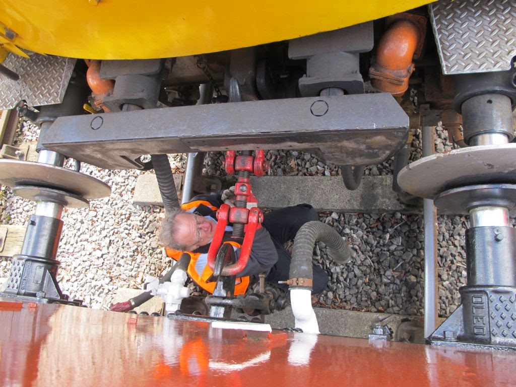
 There was a bit of a struggle to release the vacuum brake pipe on the 33. A large screw driver used as a lever eventually did the job. 33102 is fitted with 'push pull' gear so has a rubbing plate and extra pipework, all making this job more difficult in the even more confined space available.

 Then, the screw coupling is hooked on and wound up to adjustment

I rode the train back to Consall to spend more time with Emma, Russ, and the new token system.


Sunday

This morning I drove to Cheddleton to travel to Consall on 'Sophie', with Emma.

Travelling down to Consall in Sophie's cab this morning

As yesterday morning, there was a problem switching in the box. Here Emma has the token machine case off to sort it while Sophie idles loudly outside with her distinctive irregular beat. 

The N7 approaches Consall box from Froghall 

The 'Titfield Thunderbolt' (the nickname for the weekend for the passenger train with a goods brake van) waits at Consall as the N7 runs in from Cheddleton 

A Wookie, a Darlek, and two Dr Whos at Consall 

This Wookie seems fixated on my facing point lock lever for the no.6 points

A storm Trooper and Darth Vader patrol the Consall platform 

Dave Gibson's picture of the N7 train in the valley 

Apparently there are pink female Daleks. Did they ever feature in Dr. Who? I think when I watched it decades ago it was in black and white!

 Nick, Sopie's driver, seems unconcerned at being challenged at Consall


So, a great weekend apart from iffy weather late on today, but a few problems with the new token system in switching the box in and out. It'll be interesting to see how that goes over the coming weeks.

And it's goodbye too to the N7. Not 'my kind of engine', but it's been a useful addition to the CVR fleet. 

I'll be glad when the S160 is back in service!

Here's a video I took yesterday from the brake van, of the N7 departing Consall for Froghall:

N7 leaves Consall

Sci Fi weekend, a selection of the Dramtis Personae
.